US Patent 7,791,353 B2
Introduction
Simple Circuit Concepts
Transmission lines
Faraday's law
Near and far fields
Spurious coupling mechanisms
- Direct conduction
- Capacitive coupling -problem
- Capacitive coupling -fixing
- Inductive coupling-problem
- Inductive coupling -fixing by twisted
- Inductive coupling -fixing by coax
- Electromagnetic pickup
- Examples
- Safety & star grounding
- Gnd loop resistance, inductance
- Low frequency behavior
- High frequency behavior
- Troubleshooting
- Methods for removing
Ground loops at high frequency
Ground loop behavior at high frequencies is quite different from low frequency behavior and depends very much on the geometric symmetry of the exciting flux. High frequency behavior occurs when f, the frequency of the ground loop current, greatly exceeds the ratio Rloop/2pLloop where Rloop and Lloop are respectively the resistance and inductance of the ground loop. In this limit the induced ground loop current produces a magnetic flux nearly equal and opposite to the externally imposed flux so the net flux linked by the ground loop is nearly zero. The ground loop acts as a "flux conserver" because its net linked flux always stays the same, namely zero. This occurs if 2pf Lloop >> Rloop and in this case the magnetic flux produced by the ground loop current (red ellipse in Fig. 13) nearly cancels the externally imposed flux (blue circle in Fig. 13) so Vloop becomes nearly zero.
Ground loop behavior at high frequencies is quite different from low frequency behavior and depends very much on the geometric symmetry of the exciting flux. High frequency behavior occurs when f, the frequency of the ground loop current, greatly exceeds the ratio Rloop/2pLloop where Rloop and Lloop are respectively the resistance and inductance of the ground loop. In this limit the induced ground loop current produces a magnetic flux nearly equal and opposite to the externally imposed flux so the net flux linked by the ground loop is nearly zero. The ground loop acts as a "flux conserver" because its net linked flux always stays the same, namely zero. This occurs if 2pf Lloop >> Rloop and in this case the magnetic flux produced by the ground loop current (red ellipse in Fig. 13) nearly cancels the externally imposed flux (blue circle in Fig. 13) so Vloop becomes nearly zero.
Find ground loops fast!
-eliminate electical interference, fix star grounding
-eliminate electical interference, fix star grounding
US Patent 7,791,353 B2
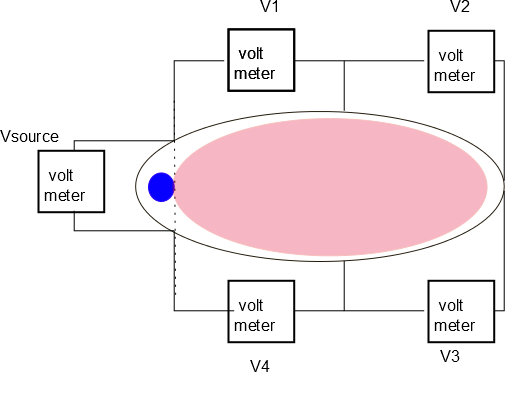
Figure 13. Blue circle represents magnetic flux produced by external currents, red ellipse represents magnetic flux produced by current flowing in ground loop (circle and ellipse overlap in reality).
However, Vloop being zero does not prevent production of an interference signal if, as is typical, the linked flux is geometrically non-uniform. Figure 13 illustrates what happens. The blue circle with area Ablue in Figure 13(a) shows localized magnetic flux induced by an external circuit in the flux-conserving ground loop; the large red ellipse with area Ared shows the flux produced by the current flowing around the ground loop. Since these fluxes are equal and opposite, i.e., Bblue Ablue +Bred Ared =0, the magnetic field Bblue in the blue circle is stronger than the magnetic field in the red ellipse by the ratio Ared/Ablue. The situation now is very much like Kirchoff's law since the region to the left of the vertical dashed line contains mainly external flux Fblue and so can be considered as a voltage source Vsource = -dFblue/dt. The region to the right of the vertical dashed line can be considered as an inductive load driven by Vsource. The current driven in this load is determined by Vsource =Lloop dIloop/dt and the voltage on any segment of the loop will be given by the proportion of total inductance associated with that section. Thus, Vsource in Fig. 13 is due to the time derivative of Fblue, while V2-V4 are due to L2 dIloop/dt, L3 dIloop/dt etc. where L2 is the inductance associated with segment 2, etc. Thus, if segment 2 is the shield of a sensor cable, a spurious signal of magnitude Vsource L2/L where L=L1+L2+L3+L4 will add to the sensor voltage.
Since the inductance of typical cables is tens of microhenries and their resistance is tens of milliohms, it is seen that Rloop/2pLloop ~100 Hz. Thus, ground loops will have a low frequency type of behavior for frequencies much less than ~100 Hz and high frequency behavior for frequencies much greater than ~100 Hz. A complex waveform has a frequency spectrum spanning both the high and low frequency ranges. For high frequencies, reducing resistance has no effect at all since only inductance matters and this depends on geometry, not material composition. Because ground loop signals depend on so many parameters (source of external flux, frequency, resistance, loop inductance, source flux geometry) the character of the ground loop interference signal is difficult to predict and could change if cables are moved around. It is therefore best to eliminate the ground loop to avoid this essentially uncontrolled interference.
Since the inductance of typical cables is tens of microhenries and their resistance is tens of milliohms, it is seen that Rloop/2pLloop ~100 Hz. Thus, ground loops will have a low frequency type of behavior for frequencies much less than ~100 Hz and high frequency behavior for frequencies much greater than ~100 Hz. A complex waveform has a frequency spectrum spanning both the high and low frequency ranges. For high frequencies, reducing resistance has no effect at all since only inductance matters and this depends on geometry, not material composition. Because ground loop signals depend on so many parameters (source of external flux, frequency, resistance, loop inductance, source flux geometry) the character of the ground loop interference signal is difficult to predict and could change if cables are moved around. It is therefore best to eliminate the ground loop to avoid this essentially uncontrolled interference.